JUL 22 1968“D” MISSION RENDEZVOUS GROUND RULES WORKING AGREEMENTS AND THINGS LIKE THAT
July 22, 1968
“D” MISSION RENDEZVOUS GROUND RULES WORKING AGREEMENTS AND THINGS LIKE THAT
1. General
a. reference trajectory is that provided by MPAD dated June 24, 1968.
b. Nomenclature for the burn sequence following undocking is:
(1) RCS Separation (2) Phasing (3) Insertion (4) TPI₀ – If abort from football (5) CSI₁ (6) CDH₁ (7) TPI₁ – If abort from lst bubble (8) CSI₂ (9) CDH₂ (10) TPI₂ (11) TPF
c. The rendezvous will be run throughout with the vehicle roll angles ≈ 0°. The only exception to this is the RCS Separation burn where the CSM roll is 180°. A 180° roll will be performed by the CSM immediately prior to or during the IMU alignment following the RCS Separation burn. (i.e., TPI from above will be initiated “heads down” and TPI from below will be initiated “heads up” for either vehicle.)
d. LM and CSM state vectors time tagged 12 minutes before RCS Separation are uplinked to the CMC and LGC prior to undocking. State vectors are not sent to either vehicle again until immediately after TPI₁, when the rendezvous navigation problem is reinitialized. At that time, state vectors are sent for both spacecraft and to both computers. IMU alignments will also be made at these points in the exercise and take precedence over the state vector updates if timeline conflicts develop.
e. On both spacecraft all rendezvous navigation will be carried out to update the LM state vector. That is, the LM radar data would be used to update the LM state vector in the LGC and the CSM sextant data would be used to update the LM state vector in the CMC.
f. On both spacecraft the rendezvous navigation W-Matrix will be set to 1000 feet and 1 fps initially and whenever it is reinitialized periodically during the rendezvous.
g. The CMC's LM state vector will be updated after each LM maneuver with the R-32 Target ΔV routine using the pre-burn values as determined in the LM's pre-thrust program.
h. The AGS should be maintained in that state which makes it most useful to perform the rendezvous in the event of PGNCS failure. If, after having established the preferred techniques in accordance with that ground rule, it is possible to include some AGS systems tests without jeopardizing crew safety or other mission objectives, they would be considered.
i. The state vectors in the AGS will be updated each time PGNCS is confirmed to be acceptable. This will likely be at each time it is committed to make the next maneuver using the PGNCS except perhaps TPI.
j. AGC alignments will be made each time the PGNCS is realigned and each time the state vector in the AGS is updated from the PGNCS.
k. If PGNCS, RR, or G&N fails, the rendezvous exercise is aborted at the next TPI opportunity.
l. The AGS is not mandatory for the rendezvous exercise. That is, if it fails prior to or during this mission phase, the exercise shall continue.
2. Prior to Undocking
a. The crew will synchronize the CMC clock as precisely as possible utiliz- ing information voiced from the ground. The crew will provide initial synchro- nization of the LGC to the CMC clock. The ground will provide the necessary information by voice for fine synchronization of the LGC clock. This supercedes the mission rule which specifies resynchronization of a space- craft clock only whenever it disagrees with the ground reference by more than 0.5 seconds.
b. The LM Rendezvous REFSMMAT is that of a “nominal” alignment for T(align) = TIG (TPI₂). It will be uplinked from the ground.
c. The CSM Rendezvous REFSMMAT is defined by a stable member orientation where:
X̄ CSM = Z̄ LM Ȳ CSM = Ȳ LM Z̄ CSM = -X̄ LM
d. Prior to undocking, the CSM will maneuver the docked vehicles to an inertial attitude such that with no further attitude maneuvering the CSM will be oriented approximately 180, 0, 0, (roll, pitch, yaw) with respect to the local vertical frame at the time of the RCS Separation. The difference between the exact local vertical attitude and 180, 0, 0 is due to the regression of the line of modes from TIG (RCS Separation) to TIG (TPI₂), and the fact that the CSM REFSMMAT is nominal at TPI₂.
e. The only in-flight adjustment of the LGC PIPA bias compensation parameters included in the nominal flight plan shall be done by the crew while docked to the CSM. The values will be updated regardless of how small the change. (i.e., There is no lower threshold.) The crew will inform the MCC-H of the new values at the next MSFN station contact possible. The MCC-H will continually monitor the IMU performance and will advise and assist in additional updates if the compensation becomes in error by more than a specified threshold.
f. An AGS accelerometer calibration shall be performed while docked at about the same time as the PIPA compensation. This will be the only AGS accelerometer calibration in the nominal flight plan unless time is available for a second one between TPI₁ and CSI₂. AGS gyro calibration shall not be performed during the rendezvous exercise period of activity.
g. Prior to unlocking, but following the CSM attitude maneuver to RCS Separation attitude, the LM IMU will be aligned to the CM IMU using the docked alignment procedure which takes advantage of a known CSM inertial attitude and known CSM/LM geometry (with account of the docking ring angle Δ⌀ being taken) to coarse align the LM IMU to the inertial frame. The CSM and LM gimbal angles are then compared directly (via V16N20) and coarse align and attitude dead banding errors are removed by direct torquing of the LM IMU gyros via the fine align routine (V41).
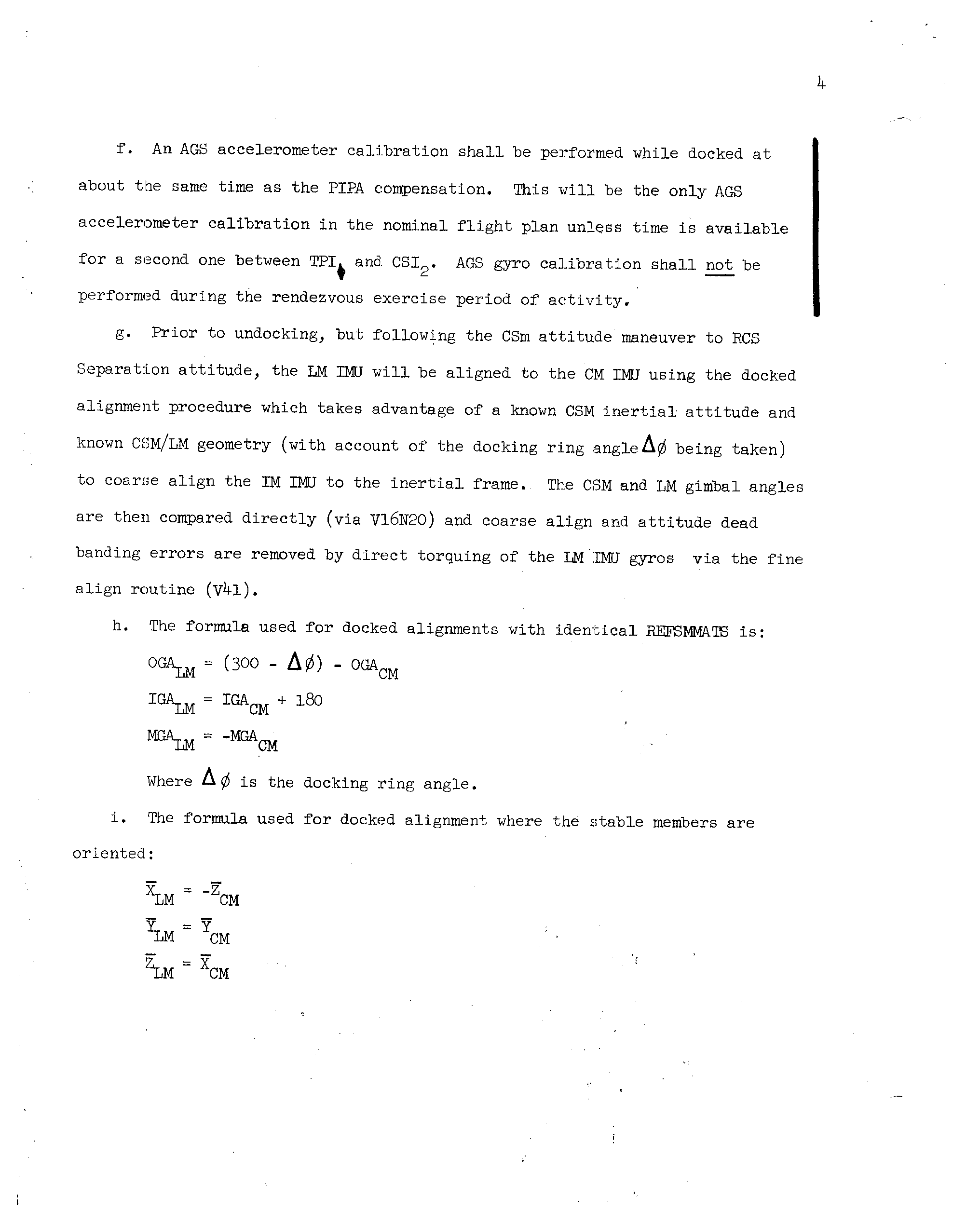
h. The formula used for docked alignment with identical REFSMMATS is:
OGALM = (300 -Δ⌀) – OGACM IGALM = IGACM + 180 MGALM = -MGACM
Where Δ⌀ is the docking ring angle.
i. The formula used for docked alignment where the stable members are oriented:
X̄LM = -Z̄CM ȲLM = ȲCM Z̄LM = X̄CM is:
CGALM = (300 -Δ⌀) – CGACM IGALM = IGACM + 90 MGALM = MGACM = 0
This is a special formula only valid where the CM MGA = 0. This set of equations will be used for the LM alignment prior to undocking. (Equation verification is given in MIT/IL Apollo G&N System Test Group Memo No. 1187, dated July 8, 1968.)
3. Undocking, station keeping and LM inspection
a. Undocking will take place 15 minutes prior to the RCS Separation burn with the CSM oriented to the inertial attitude for that burn. Average G will not be on in either vehicle during the undocking or station keeping phase. This will preserve the relative state vectors until Average G comes on in the CSM 30 seconds prior to RCS Separation.
b. Following undocking, the CSM will maintain attitude and will be responsible for station keeping. The LM will yaw right 120° and pitch up 90° placing the two spacecraft “nose-to-nose.” (crewmen “nose-to-nose”)
c. The LM will yaw through 360° ( 1°/sec) permitting the CSM to conduct a visual inspection of the landing gear and LM structure.
d. After completion of 3c, the LM assumes the station keeping task while the CSM prepares for RCS Separation.
4. RCS Separation and Mini-football
a. The configuration of the spacecraft at the RCS Separation burn will be LM leading the CSM, both heads down facing each other with zero relative velocity. (Orbit rate FDAI's – LM: 0, 180, 0 – CSM: 180, 0, 0). (FDAI total attitude is read in the order roll, pitch, yaw; IMU gimbal angles are read in the other outer, inner, middle).
b. The CSM will execute a 2.5 fps radial inward burn for the RCS Separation burn; i.e., the CSM will 2.5 fps -Z (body). This burn will employ the P-30, P-41 sequence. LM uses R-32 to update CSM state vector in the LGC. (Reference 68-FM62-229)
c. On entering darkness after the RCS Separation both spacecraft will perform REFSMMAT IMU alignments.
d. The LM COAS will be calibrated during the mini-football and will not be moved again after that.
5. Phasing Maneuver
a. Phasing targeting is established pre-flight.
b. The phasing burn will be executed under AGS control with PGNCS monitoring by use of programs 30 and 40. The throttle will be set at 10% for 15 seconds at which time it will be advanced crisply to approximately 40% and left there until auto-cutoff.
c. The horizon is used as a burn attitude check prior to the phasing burn when AGS is under control. The ground supplies the LPD pitch angle for this check.
d. Phasing burn monitoring
(1) Attitude and/or attitude rate limits are exceeded – terminate the burn.
(2) Overburn – Back up AGS engine off three (3) seconds after the PGNCS “engine off time” is indicated.
e. Upon completion of the burn, the LM shall be oriented with X-axis vertical and the y and z body axis ΔV residuals will be trimmed to zero.
6. TPI₀
a. If PGNCS, rendezvous radar, or CSM G&N fails prior to insertion but after phasing, TPI₀ is performed. As a standard operating procedure during the football rendezvous, the LM and CSM should both be targeted and prepared to execute the TPI if an abort is necessary. If the failure is LM PGNCS, AGS is used for executing TPI. A 130° transfer angle shall be used for aborts from the football rendezvous. (See action item 7 )
7. Insertion Maneuver
a. Pre-flight targeting will not be used for this maneuver. The ground procedures for determining the insertion maneuver are as follows: The MCC/ RTCC will utilize the two-impulse logic (NCC/NSR combination) to achieve the proper differential altitude. The computed value of the NCC maneuver will be used as the insertion maneuver. The NSR will be forced to occur at apogee even if station coverage will not be available there for this (CDH₁) maneuver.
b. In the event the LM has performed a ullage maneuver prior to a DPS engine failure to start, the LM will remove that ΔV to maintain correct targeting of the CSM TPI maneuver. The CSM shall continue to countdown for TPI₀ during the LM insertion burn.
8. CSI₁,₂ and CDH₁,₂
a. CSI and CDH maneuvers shall be targeted to cause TPI time to occur when the CSI is 11 minutes into darkness. TPI time is defined as the time at which the elevation angle of the CSM with respect to local horizontal as observed by the LM is 27.5° (see 9b).
b. The MCC-H will select and relay to the crew a single solution for each of the CSI and CDH rendezvous maneuvers which will be used by both space- craft – for PGNCS comparison, AGS targeting, and CSM G&N mirror image targeting, etc. It shall be that solution which is most compatible with the PGNCS. Some biases will be necessary for use in the AGS and CSM G&N.
c. As a nominal procedure, the command module will be targeted with “mirror image” maneuvers to be executed with a one minute time delay in the event the LM is unable to maneuver. In order to maintain TPI time and differential altitude within acceptable bounds it is necessary to bias the radial ΔV component of the CDH maneuvers relayed to the CSM from the MCC-H by an amount established pre-flight (approximately 7 fps). No other ΔV components of either the CSI or CDH maneuvers need to be biased in the CMC.
d. The crew shall bias CDH time 100 seconds earlier than determined by the PGNCS CSI targeting program (P32) when sequencing through the CDH tar- geting program (P33) to compensate for an inadequate approximation in P32. The crew shall bias CDH₂ time 70 seconds later than determined in P32.
e. An out-of-plane ΔV component will be computed by the LM PGNCS for CSI₂ and CDH₁,₂ using R36. This maneuver ΔV shall be executed unless it is less than 2 fps. This ΔV component will be included in the LGC/MSFN solution comparison.
f. LM PGNCS ΔV solutions will be compared with the ground. If the solutions agree, the PGNCS solution will be burned. There will not be comparisons with AGS, charts, or CSM.
g. In the event the ground solution is to be used, it will be executed using the AGS which has been targeted with the MEFN solution as a standard procedure. The external ΔV mode is used. It is necessary to bias the radial ΔV component of the CSI₂ maneuver relayed to the LM (AGS) from the MCC-H by an amount established pre-flight in order to maintain TPI₂ time within acceptable bounds. No other ΔV components of either the CSI or CDH maneuvers need to be biased in the AGS.
h. No radar data shall be input into the AGS prior to CSI and CDH.
i. There will not be any backup charts used for CSI₁,₂. The LM shall have backup charts for CDH and TPI. The CDH charts require a minimum of 29 minutes between CSI and CDH. The command module pilot will be unable to compute onboard chart solutions for TPI due to the press of other activity and so they will not be available as a data source.
j. In the event the LM has performed an ullage maneuver prior to a main engine failure, the LM will remove that ΔV to maintain correct targeting of the CSM mirror image burn.
9. TPI₀,₁,₂
a. Although studies have shown that if TPI time falls outside a window of approximately four minutes duration undesirable lighting conditions will result for one or both spacecraft, it has been established that it is more important to execute TPI at the proper elevation angle than to honor lighting constraints in terminal phase. That is lighting constraints are desirable but not mandatory. Nominal TPI elevation angle is mandatory.
b. The elevation angle to be used in the TPI targeting programs (P34) in both spacecraft shall be 27.5° for all rendezvous.
c. The LM shall always use the elevation angle option in P34 for TPI targeting.
d. The CSM shall always use the elevation angle option in P34 for TPI targeting whenever it becomes the active vehicle. Therefore, the first time the CSM cycles through P34 it will use the elevation angle option; however, if the LM TPI solution is determined to be acceptable by comparison checks, the CSM will recycle through P34 using the LM TPI time as input to the “time” option. (TPI maneuvers will not be biased.)
e. TPI shall be targeted onboard and at MCC-H to force a node at TPF (i.e., intercept). The MCC-H shall supply this maneuver via voice (pad message) in both External ΔV and line-of-sight components.
f. If the LM PGNCS is working but rendezvous radar has failed, no external data will be input to the spacecraft systems—PGNCS, AGS or charts. In this case, the command module executes the TPI and subsequent midcourse correction maneuvers and the LM does the braking maneuver if visibility permits. However, the command module, of course, must compare its TPI solution with the MSFN and that comparison must be favorable. (If not, see 9h) The command module would voice relay to the LM the maneuvers it has executed in order that the LM crew could update the command module state vector in the LGC using the target ΔV program.
g. If the LM PGNCS has failed, but the RR is working, compare the onboard chart solution for TPI with the MSFN. If the comparison is favorable, execute the chart solution and, if not, use the MSFN ΔV's executed at a time determined onboard the spacecraft. The maneuver would be made using the AGS external ΔV mode.
h. If both the RR and the CSM G&N have failed, use the LM PGNCS to execute the MSFN TPI solution given in LOS coordinates at the time at which the elevation angle is 27.5° as determined onboard the spacecraft.
- Jun 25, 1968 – “D” MISSION RENDEZVOUS GROUND RULES WORKING AGREEMENTS AND THINGS LIKE THAT (13.4σ)
- Sep 23, 1968 – D Rendezvous Ground Rules and Working Agreements update (7.3σ)
tindallgrams01.pdf