Upthread: D Rendezvous Mission Techniques Meeting – September 9, 1968 (Sep 12, 1968)
Downthread: D Rendezvous Mission Techniques (Oct 10, 1968)
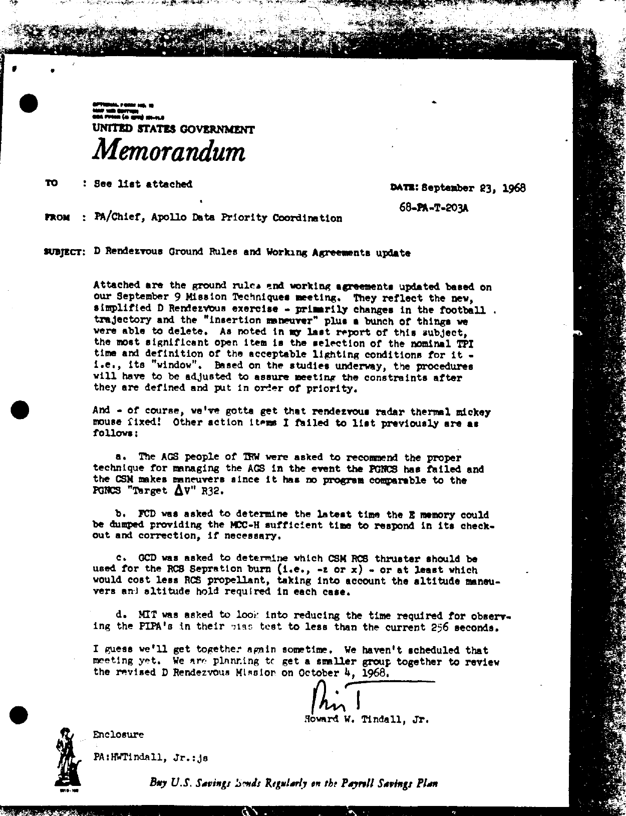
See list attachedSeptember 23, 196868-PA-T-203APA/Chief, Apollo Data Priority CoordinationD Rendezvous Ground Rules and Working Agreements update
Attached are the ground rules and working agreements updated based on our September 9 Mission Techniques meeting. They reflect the new, simplified D Rendezvous exercise – primarily changes in the football trajectory and the “insertion maneuver” plus a bunch of things we were able to delete. As noted in my last report of this subject, the most significant open item is the selection of the nominal TPI time and definition of the acceptable lighting conditions for it – i.e., its “window”. Based on the studies underway, the procedures will have to be adjusted to assure meeting the constraints after they are defined and put in order of priority.
And – of course, we've gotta get that rendezvous radar thermal mickey mouse fixed! Other action items I failed to list previously are as follows:
a. The AGS people of TRW were asked to recommend the proper technique for managing the AGS in the event the PGNCS has failed and the CSM makes maneuvers since it has no program comparable to the PGNCS “Target ΔV” R32.
b. FCD was asked to determine the latest time the E memory could be dumped providing the MCC-H sufficient time to respond in its check- out and correction, if necessary.
c. GCD was asked to determine which CSM RCS thruster should be used for the RCS Separation burn (i.e., -z or x) – or at least which would cost less RCS propellant, taking into account the altitude maneu- vers and altitude hold required in each case.
d. MIT was asked to look into reducing the time required for observ- ing the PIPA's in their bias test to less than the current 256 seconds.
I guess we'll get together again sometime. We haven't scheduled that meeting yet. We are planning to get a smaller group together to review the revised D Rendezvous Mission on October 4, 1968.
Enclosure
September 12, 1968
“D” MISSION RENDEZVOUS GROUND RULES, WORKING AGREEMENTS AND THINGS LIKE THAT
1. General
a. The reference trajectory is that provided by MPAD, dated August 22, 1968, and as amplified in Appendix I.
b. Nomenclature for the burn sequence following undocking is:
(1) RCS Separation (2) Phasing (3) TPI₀ – If abort from football (4) Insertion (5) CSI (6) CDH (7) TPI (8) TPF
c. The rendezvous will be run throughout with the vehicle roll angles ≈ 0°. The only exception to this is the RCS Separation burn where the CSM roll is 180°. A 180° roll will be performed by the CSM immediately prior to or during the IMU alignment following the RCS Separation burn. (i.e., TPI from above will be initiated “heads down” and TPI from below will be initiated “heads up” for either vehicle.)
d. LM and CSM state vectors time tagged 12 minutes before RCS Separation are uplinked to the CMC and LGC prior to undocking. State vectors are not sent to either vehicle again during the rendezvous.
e. On both spacecraft all rendezvous navigation will be carried out to update the LM state vector. That is, the LM radar data would be used to update the LM state vector in the LGC and the CSM sextant data would be used to update the LM state vector in the CMC.
f. On both spacecraft the rendezvous navigation W-matrix will be set to 1000 feet and 1 fps initially and whenever it is reinitialized periodically during the rendezvous.
g. The CMC's LM state vector will be updated after each LM maneuver with the P-76 Target ΔV routine using the pre-burn values as determined in the LM's pre-thrust program
h. The AGS should be maintained in that state which makes it most useful to perform the rendezvous in the event of PGNCS failure. If, after having established the preferred techniques in accordance with that ground rule, it is possible to include some AGS systems tests without jeopardizing crew safety or other mission objectives, they would be considered.
i. The state vectors in the AGS will be updated each time PGNCS is confirmed to be acceptable. This will likely be at each time it is committed to make the next maneuver using the PGNCS except perhaps TPI.
j. AGC alignments will be made each time the PGNCS is realigned and each time the state vector in the AGS is updated from the PGNCS.
k. If PGNCS, RR, or G&N fails while in the football trajectory, the rendezvous exercise is terminated at the TPI₀ opportunity.
l. The AGS is not mandatory for the rendezvous exercise. That is, if it fails prior to or during this mission phase, the exercise shall continue.
m. As soon as possible after powering up the LGC, the E memory will be dumped via T/M so that the MCC-H may check its contents for completeness and accuracy. If necessary, the MCC-H will reload via uplink any important parameters found to be in error.
2. Prior to Undocking
a. The crew will synchronize the CMC clock as precisely as possible utiliz- ing information voiced from the ground. The crew will provide initial synchro- nization of the LGC to the CMC clock. The ground will provide the necessary information by voice for fine synchronization of the LGC clock. This supercedes the mission rule which specifies resynchronization of a space- craft clock only whenever it disagrees with the ground reference by more than 0.5 seconds.
b. The LM Rendezvous REFSMMAT is that of a “nominal” alignment for T (align) = TIG (TPI). It will be uplinked from the ground.
c. The CSM Rendezvous REFSMMAT is defined by a stable member orientation where:
X̄ CSM = Z̄ LM Ȳ CSM = Ȳ LM Z̄ CSM = -X̄ LM
d. Prior to undocking, the CSM will maneuver the docked vehicles to an inertial attitude such that with no further attitude maneuvering the CSM will be oriented approximately 180, 0, 0, (roll, pitch, yaw) with respect to the local vertical frame at the time of the RCS Separation. The difference between the exact local vertical attitude and 180, 0, 0 is due to the regression of the line of modes from TIG (RCS Separation) to TIG (TPI), and the fact that the CSM REFSMMAT is nominal at TPI.
e. The only in-flight adjustment of the LGC PIPA bias compensation parameters included in the nominal flight plan shall be done by the crew while docked to the CSM. The values will be updated regardless of how small the change. (i.e., there is no lower threshold) The crew will inform the MCC-H of the new values at the next MSFN station contact possible. The MCC-H will continually monitor the IMU performance and will advise and assist in additional updates if the compensation becomes in error by more than a specified threshold. Currently this threshold is set at .003 ft./sec.².
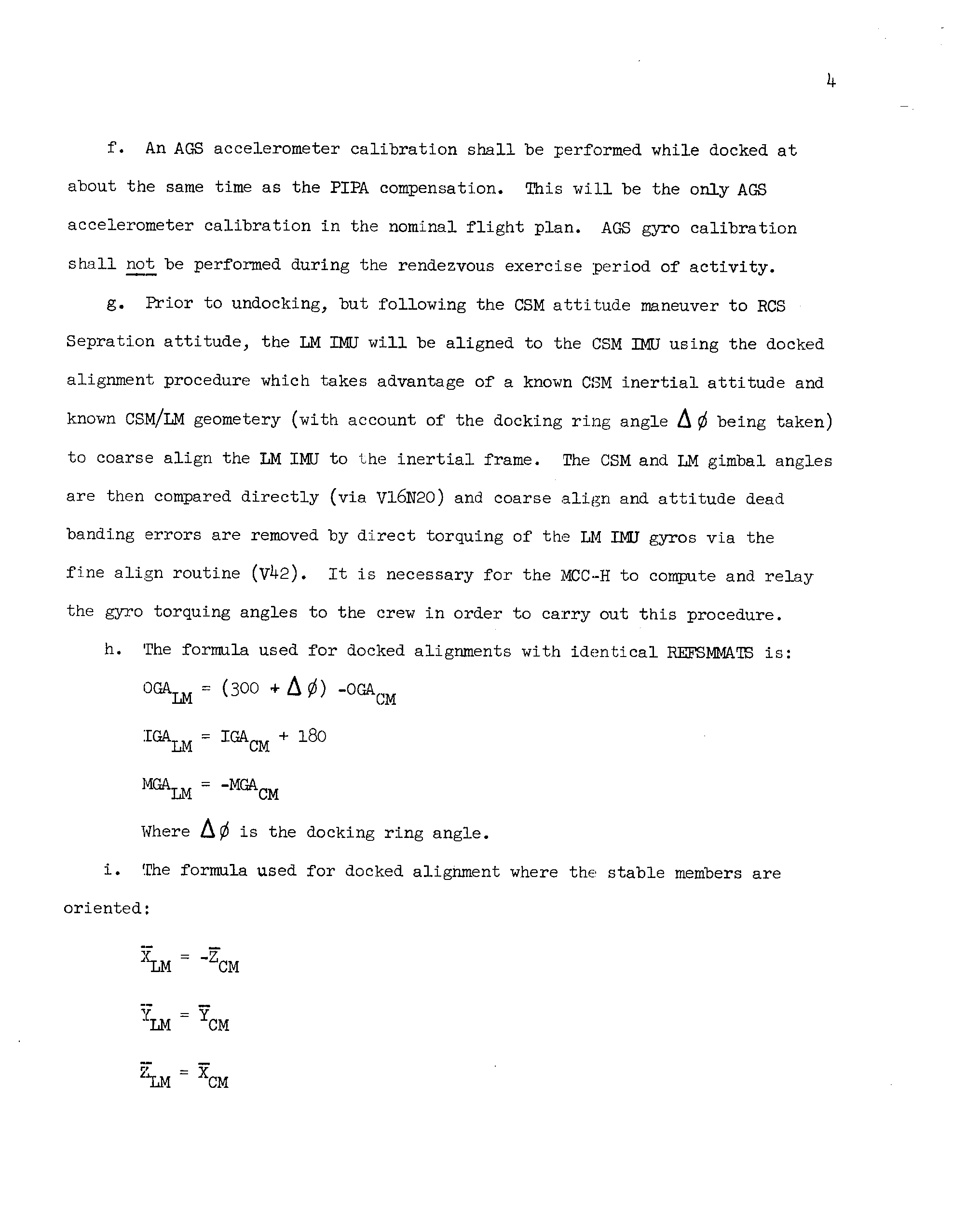
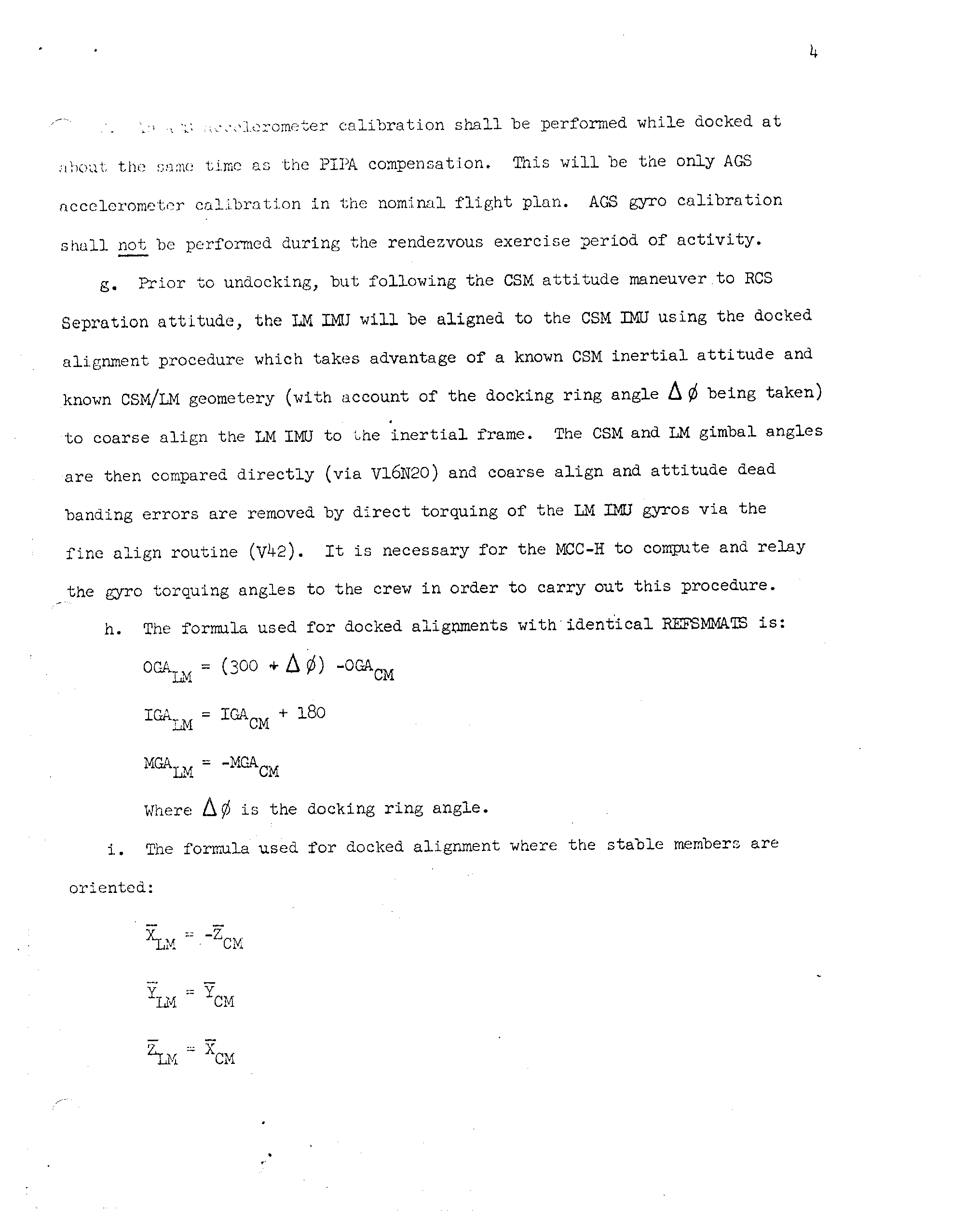
f. An AGS accelerometer calibration shall be performed while docked at about the same time as the PIPA compensation. This will be the only AGS accelerometer calibration in the nominal flight plan. AGS gyro calibration shall not be performed during the rendezvous exercise period of activity.
g. Prior to undocking, but following the CSM attitude maneuver to RCS Separation attitude, the LM IMU will be aligned to the CSM IMU using the docked alignment procedure which takes advantage of a known CSM inertial attitude and known CSM/LM geometery (with account of the docking ring angle Δ⌀ being taken) to coarse align the LM IMU to the inertial frame. The CSM and LM gimbal angles are then compared directly (via V16N20) and coarse align and attitude dead banding errors are removed by direct torquing of the LM IMU gyros via the fine align routine (V42). It is necessary for the MCC-H to compute and relay the gyro torquing angles to the crew in order to carry out this procedure.
h. The formula used for docked alignments with identical REFSMMATS is:
CGALM = (300 -Δ⌀) – CGACM IGALM = IGACM + 180 MGALM = -MGACM
Where Δ⌀ is the docking ring angle.
i. The formula used for docked alignment where the stable members are oriented:
X̄LM = -Z̄CM ȲLM = ȲCM Z̄LM = X̄CM
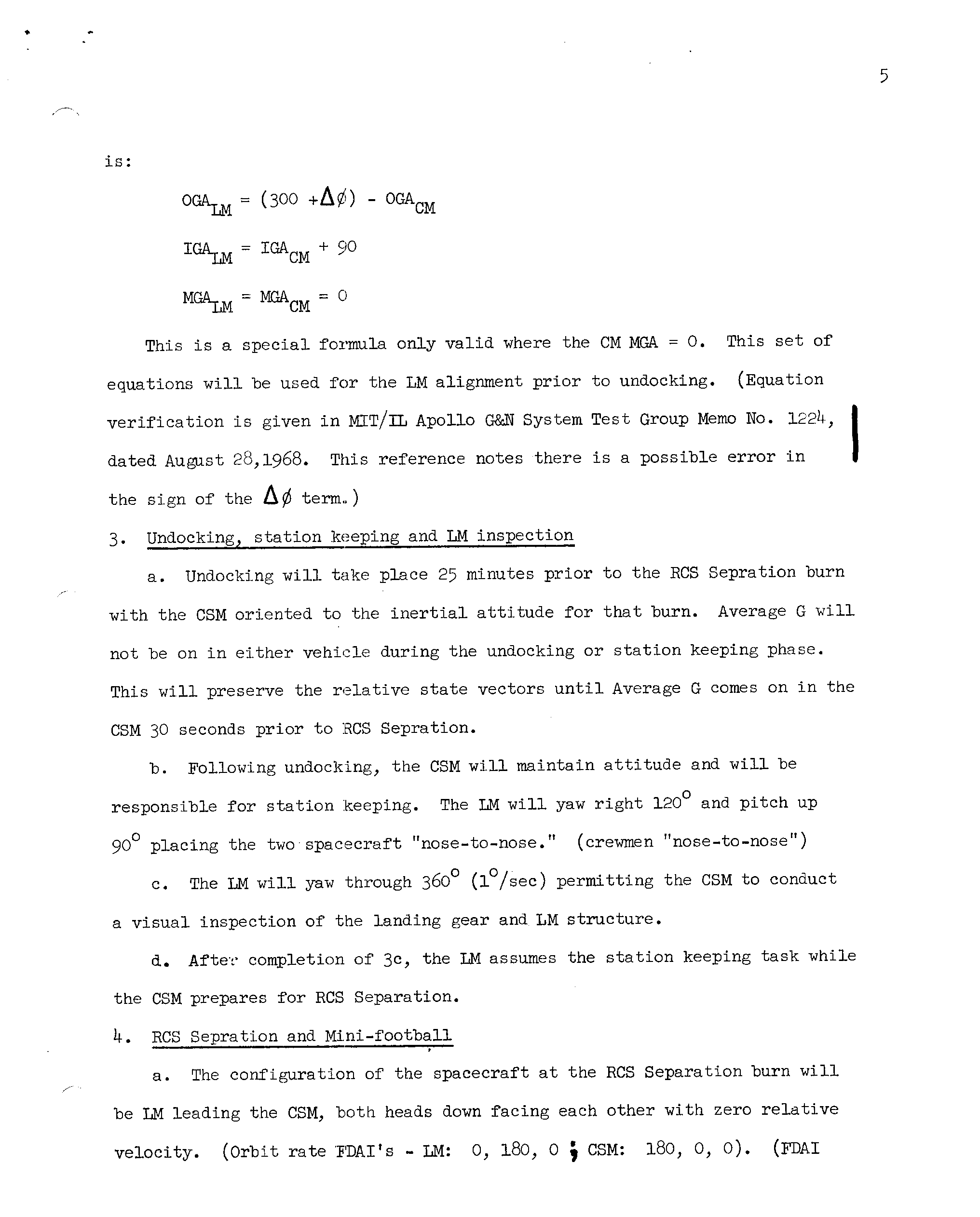
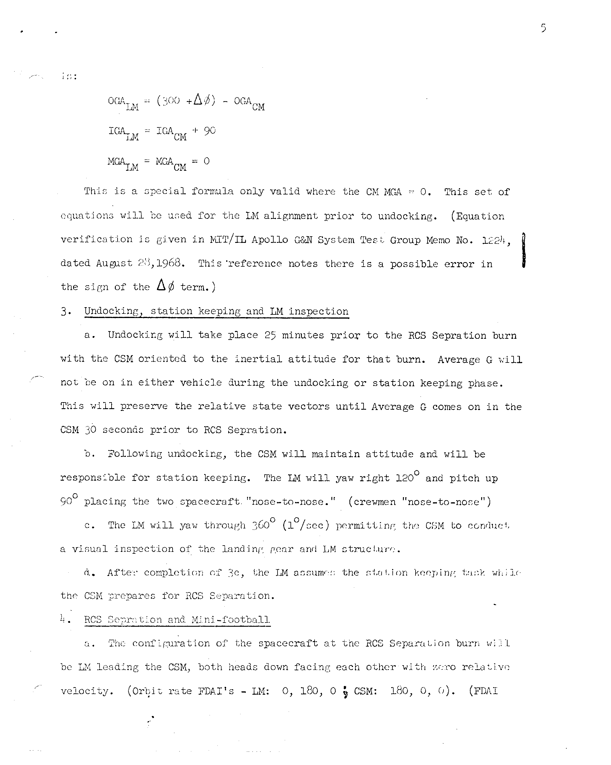
is:
CGALM = (300 -Δ⌀) – CGACM IGALM = IGACM + 90 MGALM = MGACM = 0
This is a special formula only valid where the CM MGA = 0. This set of equations will be used for the LM alignment prior to undocking. (Equation verification is given in MIT/IL Apollo G&N System Test Group Memo No. 1224, dated August 28,1968. This reference notes there is a possible error in the sign of the Δ⌀ term.)
3. Undocking, station keeping and LM inspection
a. Undocking will take place 25 minutes prior to the RCS Separation burn with the CSM oriented to the inertial attitude for that burn. Average G will not be on in either vehicle during the undocking or station keeping phase. This will preserve the relative state vectors until Average G comes on in the CSM 30 seconds prior to RCS Separation.
b. Following undocking, the CSM will maintain attitude and will be responsible for station keeping. The LM will yaw right 120° and pitch up 90° placing the two spacecraft “nose-to-nose.” (crewmen “nose-to-nose”)
c. The LM will yaw through 360° (1°/sec) permitting the CSM to conduct a visual inspection of the landing gear and LM structure.
d. After completion of 3c, the LM assumes the station keeping task while the CSM prepares for RCS Separation.
4. RCS Separation and Mini-football
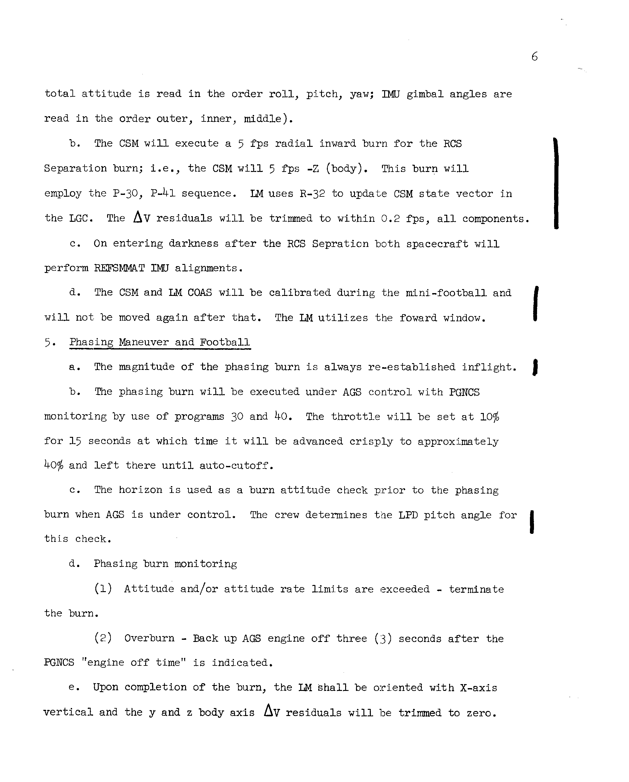
a. The configuration of the spacecraft at the RCS Separation burn will be LM leading the CSM, both heads down facing each other with zero relative velocity. (Orbit rate FDAI's – LM: 0 , 180, 0 ; CSM: 180, 0, 0). (FDAI total attitude is read in the order roll, pitch, yaw; IMU gimbal angles are read in the order outer, inner, middle).
b. The CSM will execute a 5 fps radial inward burn for the RCS Separation burn; i.e., the CSM will 5 fps -Z (body). This burn will employ the P-30, P-41 sequence. LM uses R-32 to update CSM state vector in the LGC. The ΔV residuals will be trimmed to within 0.2 fps, all components.
c. On entering darkness after the RCS Separation both spacecraft will perform REFSMMAT IMU alignments.
d. The CSM and LM COAS will be calibrated during the mini-football and will not be moved again after that. The LM utilizes the forward window.
5. Phasing Maneuver and Football
a. The magnitude of the phasing burn is always re-established inflight.
b. The phasing burn will be executed under AGS control with PGNCS monitoring by use of programs 30 and 40. The throttle will be set at 10% for 15 seconds at which time it will be advanced crisply to approximately 40% and left there until auto-cutoff.
c. The horizon is used as a burn attitude check prior to the phasing burn when AGS is under control. The crew determines the LPD pitch angle for this check.
d. Phasing burn monitoring
(1) Attitude and/or attitude rate limits are exceeded – terminate the burn.
(2) Overburn – Back up AGS engine off three (3) seconds after the PGNCS “engine off time” is indicated.
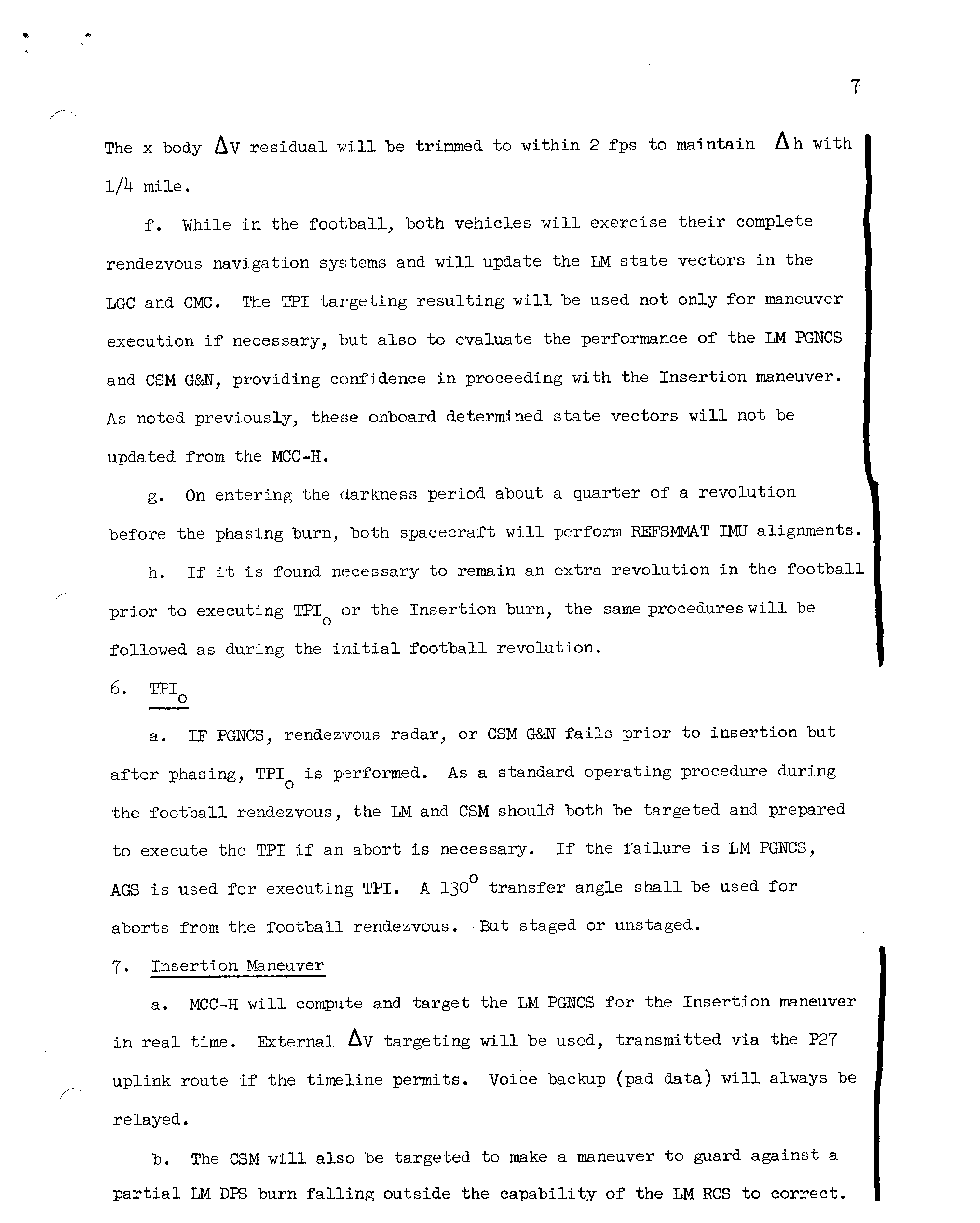
e. Upon completion of the burn, the LM shall be oriented with X-axis vertical and the y and z body axis & residuals will be trimmed to zero.
The x body ΔV residual will be trimmed to within 2 fps to maintain Δh with 1/4 mile.
f. While in the football, both vehicles will exercise their complete rendezvous navigation systems and will update the LM state vectors in the LGC and CMC. The TPI targeting resulting will be used not only for maneuver execution if necessary, but also to evaluate the performance of the LM PGNCS and CSM G&N, providing confidence in proceeding with the Insertion maneuver. As noted previously, these onboard determined state vectors will not be updated from the MCC-H.
g. On entering the darkness period about a quarter of a revolution before the phasing burn, both spacecraft will perform REFSMMAT IMU alignments.
h. If it is found necessary to remain an extra revolution in the football prior to executing TPI₀ or the Insertion burn, the same procedures will be followed as during the initial football revolution.
6. TPI₀
a. IF PGNCS, rendezvous radar, or CSM G&N fails prior to insertion but after phasing, TPI₀ is performed. As a standard operating procedure during the football rendezvous, the LM and CSM should both be targeted and prepared to execute the TPI if an abort is necessary. If the failure is LM PGNCS, AGS is used for executing TPI. A 130° transfer angle shall be used for aborts from the football rendezvous. But staged or unstaged.
7. Insertion Maneuver
a. MCC-H will compute and target the LM PGNCS for the Insertion maneuver in real time. External ΔV targeting will be used, transmitted via the P27 uplink route if the timeline permits. Voice backup (pad data) will always be relayed.
b. The CSM will also be targeted to make a maneuver to guard against a partial LM DPS burn falling outside the capability of the LM RCS to correct.
This maneuver will probably be fixed preflight (for example – 20 fps, horizontal, posigrade) which would permit the LM to return to a football by RCS.
c. In the event the LM has performed a ullage maneuver prior to a DPS engine failure to start, the LM will remove that ΔV to stay in the football.
8. CSI and CDH
a. CSI and CDH maneuvers shall be targeted to cause TPI time to occur when the CSM is 25½ minutes before sunrise. TPI time is defined as the time at which the elevation angle of the CSM with respect to local horizontal as observed by the LM is 27.5° (see 9b).
b. The MCC-H will select and relay to the crew a single solution for each of the CSI and CDH rendezvous maneuvers which will be used by both spacecraft – for PGNCS comparison, AGS targeting, and CSM G&N mirror image targeting, etc. It shall be that solution which is most compatible with the PGNCS. Some biases will be necessary for use in the CSM G&N.
c. As a nominal procedure, the command module will be targeted with “mirror image” maneuvers to be executed with a one minute time delay in the event the LM is unable to maneuver. In order to maintain TPI time and differential altitude within acceptable bounds it is necessary to bias the radial ΔV component of the CDH maneuver relayed to the CSM from the MCC-H by an amount established pre-flight(probably 4.3 fps). No other ΔV component of either the CSI or CDH maneuvers need to be biased in the CMC.
d. In order to compensate for approximations in the onboard CSI tar- geting program (P32) resulting in a “nominal” TPI time shift, it is necessary to bias the TPI time the LM crew inputs to that program 120 seconds late. The crew shall bias CDH time 110 seconds later than determined by the PGNCS CSI targeting program (P32) when sequencing through the CDH targeting program (P33) to compensate for an approximation in P32 which would cause a large radial component if uncorrected.
e. An out-of-plane ΔV component will be computed by the LM PGNCS for CSI and CDH using R36. This maneuverΔV shall be executed unless it is less than 2 fps. This ΔV component will be included in the LGC/MSFC solu- tion comparison.
f. LM PGNCS ΔV solutions will be compared with the ground. If the solutions agree, the PGNCS solution will be burned. There will not be comparisons with AGC, charts, or CSM.
g. In the event the ground solution is to be used, it will be executed using the AGS which has been targeted with the MSFN solution as a standard procedure. The external ΔV mode is used. No ΔV components of either the CSI or CDH maneuvers need to be biased in the AGC.
h. No radar data shall be input into the AGS prior to CSI and CDH.
i. There will not be any backup charts used for CSI. The LM shall have backup charts for CDH and TPI. The CDH charts require a minimum of 29 minutes between CSI and CDH. The command module pilot will be unable to compute onboard chart solutions for TPI due to the press of other activity and so they will not be available as a data source.
j. In the event the LM has performed an ullage maneuver prior to a main engine failure, the LM will remove that ΔV to maintain correct target- ing of the CSM mirror image burn.
9. TPI
[NOTE: Some of the following items (e.g., 9a and 9c) which involve lighting constraints have not been established as being right, since they are based on an assumption that lighting is not mandatory. In fact, the lighting is currently considered mandatory under certain circumstances. These items are included here to draw attention to this extremely important matter. It is all to be resolved as soon as results of analysis to determine firm lighting requirements and expected TPI time dispersions are available. Consideration is being given to shifting to the P34 TPI “time option” from the “elevation option” if necessary to force TPI to occur within the window. This business also has implications on 9d regarding the CSM procedures and the MCC-H solutions transmitted for comparison. These results of these studies may also cause a change in the nominal TPI time noted in 8a.]
a. Although studies have shown that if TPI time falls outside a window of approximately four minutes duration undesirable lighting conditions will result for one or both spacecraft, it has been established that it is more important to execute TPI at the proper elevation angle than to honor lighting constraints in terminal phase. That is, lighting constraints are desirable but not mandatory. Nominal TPI elevation angle is mandatory. (See note above)
b. The elevation angle to be used in the TPI targeting programs (P34) in both spacecraft shall be 27.5° for all rendezvous. A 130° transfer angle will be used for all rendezvous.
c. The LM shall always use the elevation angle option in P34 for TPI targeting. (See note above)
d. The CSM shall always use the elevation angle option in P34 for TPI targeting whenever it becomes the active vehicle. Therefore, the first time the CSM cycles through P34 it will use the elevation angle option; however, if the LM TPI solution is determined to be acceptable by com- parison checks, the CSM will recycle through P34 using the LM TPI time as input to the “time option.” (TPI maneuvers will not be biased.)
e. TPI shall be targeted onboard and at MCC-H to force a node at TPF (i. e., intercept). The MCC-H shall supply this maneuver via voice (pad message) in both External ΔV and line-of-sight components.
f. If the LM PGNCS is working but rendezvous radar has failed, no external data will be input to the spacecraft systems—-PGNCS, AGS, or charts. In this case, the command module executes the TPI and subsequent midcourse correction maneuvers and the LM does the braking maneuver if visibility permits. However, the command module, of course, must compare its TPI solution with the MSFN and that comparison must be favorable. (If not, see 9h) The command module would voice relay to the LM the maneuvers it has executed in order that the LM crew could update the command module state vector in the LGC using the target ΔV program.
g. If the LM PGNCS has failed, but the RR is working, compare the onboard chart solution for TPI with the MSFN. If the comparison is favorable execute the chart solution and, if not, use the MSFN ΔV's executed at a time determined onboard the spacecraft. The maneuver would be made using the AGS external ΔV mode.
h. If both the RR and the CSM G&N have failed, use the LM PGNCS to execute the MSFN TPI solution given in LOS coordinates at the time at which the elevation angle is 27.5° as determined onboard the spacecraft.
i. If the CSM performs the TPI maneuver, RCS will be used rather than SPS as the propulsion system. This simplification significantly reduces the CSM crew loading and gives greater assurance he will be able to do all things required of him.
- Jun 25, 1968 – “D” MISSION RENDEZVOUS GROUND RULES WORKING AGREEMENTS AND THINGS LIKE THAT (8.0σ)
- Jul 22, 1968 – “D” MISSION RENDEZVOUS GROUND RULES WORKING AGREEMENTS AND THINGS LIKE THAT (7.3σ)
- Jun 21, 1968 – Request to check some IMU alignment equations (3.1σ)
1968_tindallgrams.pdf


tindallgrams01.pdf


tindallgrams01.pdf